1:400 BEA/BA Engineering Base - Barison400

The final area of detail for the Cathdral Hangar is a little electricity substation/plant room housing the machinery to operate those giant shutter doors. The clear height of these is 70ft in old money, or just over 21 metres! Here are some photos of the test-build. Some additional parts were printed to allow details on the roof to be modelled in 3D.
 

Attachments

  • IMG_2119.JPG
    IMG_2119.JPG
    5 MB · Views: 7
  • IMG_1761.JPG
    IMG_1761.JPG
    5.4 MB · Views: 6
  • IMG_1762.JPG
    IMG_1762.JPG
    4.9 MB · Views: 4
  • IMG_1763.JPG
    IMG_1763.JPG
    5.2 MB · Views: 4
  • IMG_1764.JPG
    IMG_1764.JPG
    5.1 MB · Views: 4
  • IMG_1765.JPG
    IMG_1765.JPG
    5.4 MB · Views: 4
  • IMG_1766.JPG
    IMG_1766.JPG
    5.5 MB · Views: 3
  • IMG_1769.JPG
    IMG_1769.JPG
    5.4 MB · Views: 4
  • IMG_1771.JPG
    IMG_1771.JPG
    5.8 MB · Views: 4
Adding the 3D detail for the roof:
 

Attachments

  • IMG_2120.JPG
    IMG_2120.JPG
    4.5 MB · Views: 4
  • IMG_2121.JPG
    IMG_2121.JPG
    5.1 MB · Views: 3
  • IMG_2122.JPG
    IMG_2122.JPG
    4.8 MB · Views: 3
  • IMG_2123.JPG
    IMG_2123.JPG
    5.2 MB · Views: 3
The completed model in position with the hangar.
 

Attachments

  • IMG_2124.JPG
    IMG_2124.JPG
    3.7 MB · Views: 4
  • IMG_2126.JPG
    IMG_2126.JPG
    3.9 MB · Views: 3
  • IMG_2127.JPG
    IMG_2127.JPG
    3.7 MB · Views: 3
  • IMG_2129.JPG
    IMG_2129.JPG
    3.6 MB · Views: 3
  • IMG_2128.JPG
    IMG_2128.JPG
    3.6 MB · Views: 3
Some comparisons of the 1:1 and also a completed neighbouring workshop of the original 1952 BEA Base, onto which the Cathedral was built.
 

Attachments

  • 567A38B2-0531-445C-807F-DD84BAE5C681.jpg
    567A38B2-0531-445C-807F-DD84BAE5C681.jpg
    3.5 MB · Views: 4
  • IMG_3143.JPG
    IMG_3143.JPG
    4.2 MB · Views: 4
  • IMG_3137.jpg
    IMG_3137.jpg
    4.5 MB · Views: 4
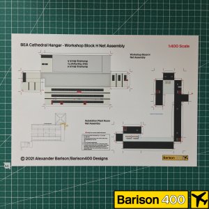
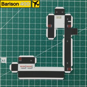
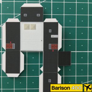
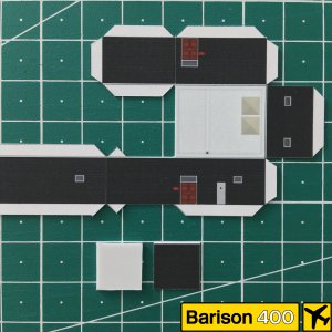
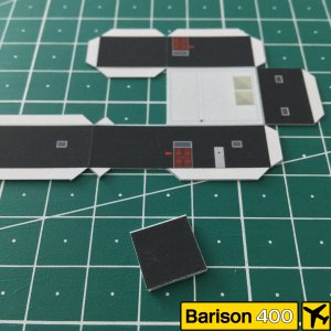
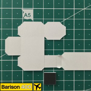
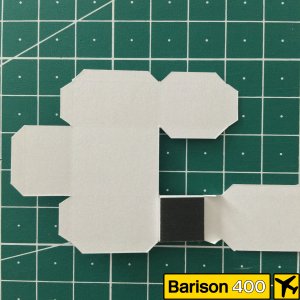
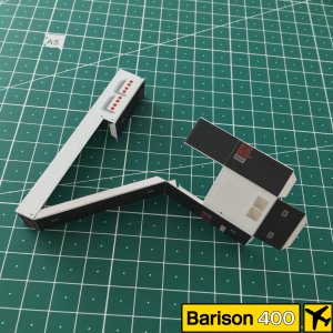
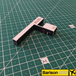
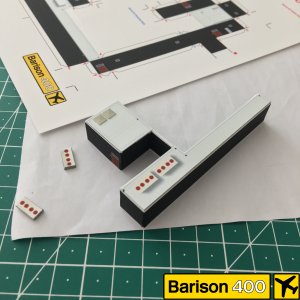
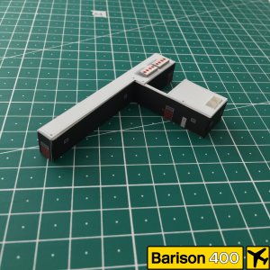
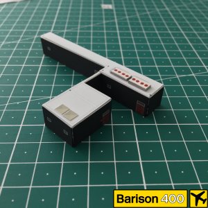
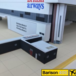
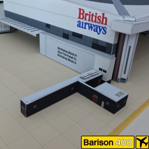
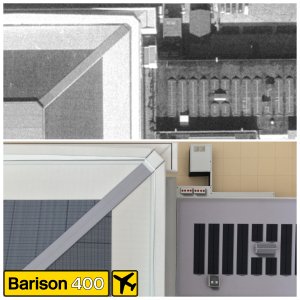
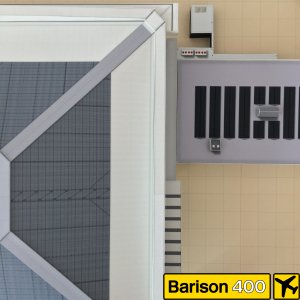
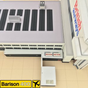
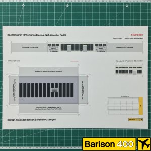
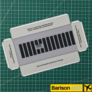
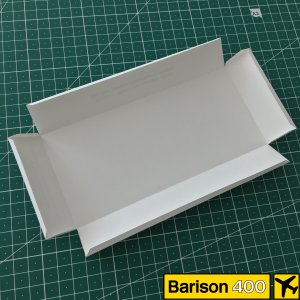
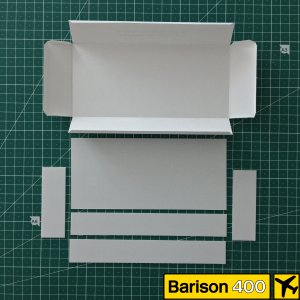
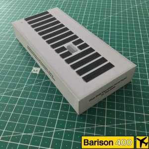
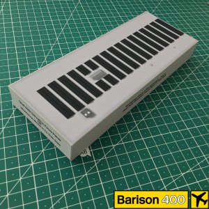
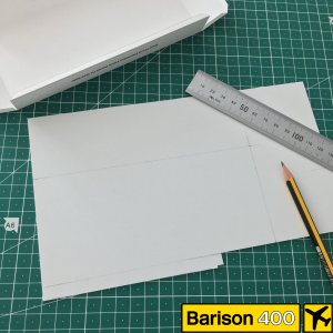
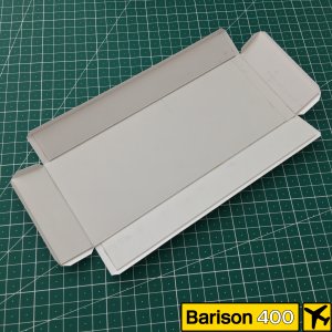
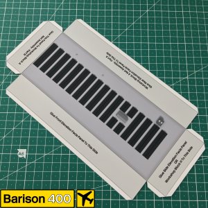
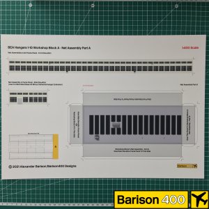
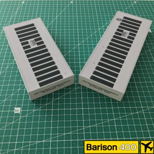
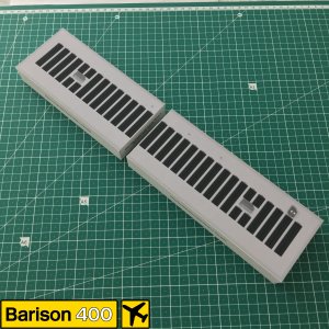
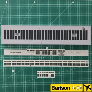
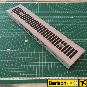
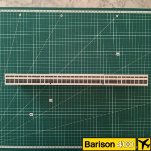
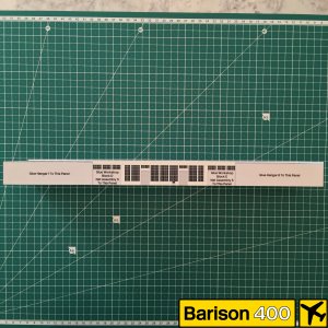
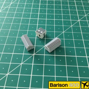
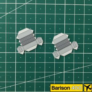
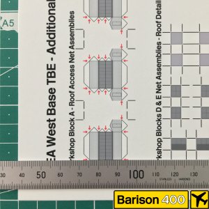
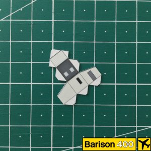
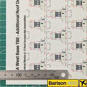
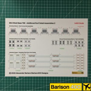
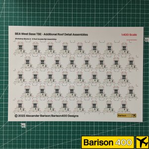
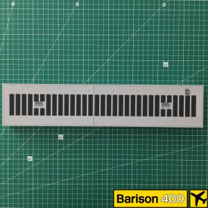
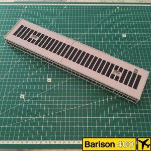
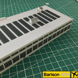
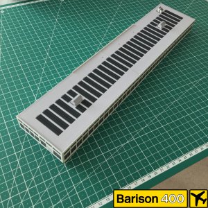
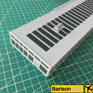
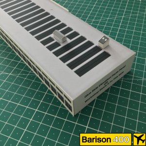
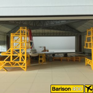
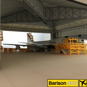
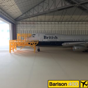
Creating a 1:400 model of a 1952 workshop block from a designed kit template. This model is quite long - both hangar pens 1-5 & 6-10 (facing outwards from each other and backed by further workshop blocks) were built onto this large block. Therefore the net assembly is split into 2 parts, following the actual building join of the 1:1. For these net assembly kits, it is neccessary to line the inside with a strengthening material. This part has been trial and error. I initially used 1mm thick styrene, which worked very well for the roof but ended up being rather concaved for the walls, which was not the desired effect! I will try this again using sheets of Obeche wood at 1.5mm thick, and see if the results are better. These kits have separate panels for the external details, which need to be mounted carefully. However they hide the joins and allow for the detail of a retaining wall surrounding the roof, which again can be lined with a modelling wood, painted to suit. I will post details of all these additional stages as I complete them.
 

Attachments

  • IMG_2918.JPG
    IMG_2918.JPG
    5.1 MB · Views: 3
  • IMG_2920.JPG
    IMG_2920.JPG
    5.1 MB · Views: 2
  • IMG_2921.JPG
    IMG_2921.JPG
    5 MB · Views: 2
  • IMG_2923.JPG
    IMG_2923.JPG
    4.7 MB · Views: 2
  • IMG_2925.JPG
    IMG_2925.JPG
    5.2 MB · Views: 2
1952 BEA Workshop Block A Net Assembly:
 

Attachments

  • IMG_2133.JPG
    IMG_2133.JPG
    5.6 MB · Views: 2
  • IMG_2922.JPG
    IMG_2922.JPG
    4.5 MB · Views: 2
  • IMG_2132.JPG
    IMG_2132.JPG
    4.8 MB · Views: 2
  • IMG_2131.JPG
    IMG_2131.JPG
    5.2 MB · Views: 2
  • IMG_2130.JPG
    IMG_2130.JPG
    4.7 MB · Views: 2
1952 BEA Workshop Block A Net Assembly:
 

Attachments

  • IMG_2927.JPG
    IMG_2927.JPG
    5.6 MB · Views: 2
  • IMG_2926.JPG
    IMG_2926.JPG
    5.8 MB · Views: 2
  • IMG_2931.JPG
    IMG_2931.JPG
    5.8 MB · Views: 2
  • IMG_2933.JPG
    IMG_2933.JPG
    6 MB · Views: 2
  • IMG_2935.JPG
    IMG_2935.JPG
    6.2 MB · Views: 2
  • IMG_2936.JPG
    IMG_2936.JPG
    6.2 MB · Views: 2
Additional net assembly sheets allow these details for the roof to be modelled in 3D:
 

Attachments

  • IMG_2956.JPG
    IMG_2956.JPG
    5.6 MB · Views: 2
  • IMG_2955.JPG
    IMG_2955.JPG
    5.4 MB · Views: 2
  • IMG_2954.JPG
    IMG_2954.JPG
    4.8 MB · Views: 2
  • IMG_2953.JPG
    IMG_2953.JPG
    5.3 MB · Views: 2
  • IMG_2952.JPG
    IMG_2952.JPG
    5 MB · Views: 2
  • IMG_2951.JPG
    IMG_2951.JPG
    5.2 MB · Views: 2
  • IMG_2950.JPG
    IMG_2950.JPG
    5.4 MB · Views: 3
...and here with these addtional details added:
 

Attachments

  • IMG_2928.JPG
    IMG_2928.JPG
    5.9 MB · Views: 3
  • IMG_2932.JPG
    IMG_2932.JPG
    6.1 MB · Views: 3
  • IMG_2959.JPG
    IMG_2959.JPG
    5.5 MB · Views: 3
  • IMG_2960.JPG
    IMG_2960.JPG
    6.8 MB · Views: 2
  • IMG_2957.JPG
    IMG_2957.JPG
    5.9 MB · Views: 2
  • IMG_2958.JPG
    IMG_2958.JPG
    5.5 MB · Views: 2
Members of the BA 747 fleet were also occassional visitors to the Cathedral Hangar, presumably when slots at their dedicated Technical Blocks J & K (built in 1970 for BOAC) were full up. This is demonstrated here by Jakarta incident veteran G-BDXH, a B.747-236 (BB400, released 2005).
 

Attachments

  • IMG_3017.JPG
    IMG_3017.JPG
    4.5 MB · Views: 2
  • IMG_3018.JPG
    IMG_3018.JPG
    4.8 MB · Views: 2
  • IMG_3019.JPG
    IMG_3019.JPG
    4.5 MB · Views: 3
  • IMG_3134.JPG
    IMG_3134.JPG
    3.8 MB · Views: 5
  • IMG_3135.JPG
    IMG_3135.JPG
    3.9 MB · Views: 7
Members of the BA 747 fleet were also occassional visitors to the Cathedral Hangar, presumably when slots at their dedicated Technical Blocks J & K (built in 1970 for BOAC) were full up. This is demonstrated here by Jakarta incident veteran G-BDXH, a B.747-236 (BB400, released 2005).
Wow... The 747 just looks like it belongs there. I am impressed
 
The Cathedral was built in anticipation of BEA's first widebody addition to the fleet - the Tristar - which whilst ordered by BEA but arrived after the merger with BOAC had taken effect and so were delivered in the first British Airways livery.
Before the Cathedral's construction and before the BEA logos and British European Airways titles were changed to British Airways, the 'BEA' logos, when illuminated at night, used to display 'FLY BEA'. The word FLY was displayed for some seconds whilst BEA was suppressed then the letters B, E and then A came on sequentially so the combined effect was 'FLY B E A'. I always thought as a kid that this was pretty cool.
 
Top